This morning, I was wondering why Ethernet frames must have a minimum length of 64 bytes. After doing some research, I quickly came across explanations involving CSMA/CD and collision detection time. However, I couldn’t find a clear, concise resource that brought all the information together, so I decided to summarize it here in case it helps someone else with the same question.
Ethernet Frames layout
First of all, here’s what a standard Ethernet frame looks like. If you’d like to dive deeper into the details of the Ethernet header fields, you can check out this other post.
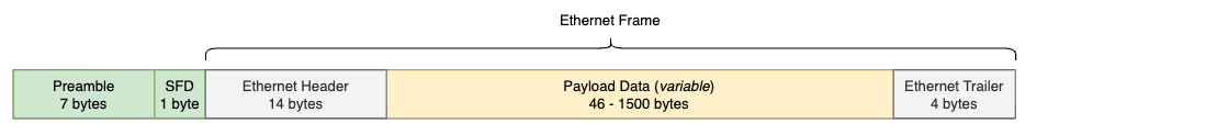
We know there are 18 bytes of unavoidable Ethernet overhead, but there’s still a gap before reaching the minimum frame size of 64 bytes.
Why does Ethernet require padding the Payload Data with up to 46 bytes in order to reach that minimum frame length ?
Let’s take a quick step back in time to recall the original context.
Xerox PARC - Robert Metcalfe - 70’s
In 1973, Robert Metcalfe (who had joined PARC in 1972) was tasked with designing a network to connect the center’s new personal computers (the Xerox Alto) to a shared laser printer located on the other side of the corridor and considered “difficult to access.”
This challenge led to the creation of Ethernet, first introduced in a memo called “Alto Ethernet”, which outlined a system based on coaxial cables and packet switching.
By mid-1975, PARC had deployed a robust 100-node Ethernet network.
However, one downside of coaxial cables is that they can only carry one signal at a time. If two nodes transmitted simultaneously, a collision would occur.
With a 100-node Ethernet network, they needed a way to detect and handle these collisions.
CSMA/CD : Carrier Sense Multiple Access with Collision Detection
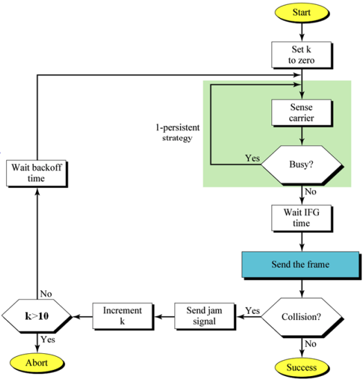
CSMA was designed to detect ongoing transmissions on the coaxial cables using carrier sensing, so a station would only transmit if no one else was already transmitting.
“Carier-sensing” means the NIC continuously monitors the coaxial cables for electrical signals that indicate an active transmission.
However, if the medium (coax cable) appears clear for a short time (microseconds, milliseconds, even seconds), multiple stations might start transmitting at the exact same moment, causing collisions somewhere along the path. That’s where CD comes in. It was designed to solve this problem by introducing a “listen while talking” mechanism : while transmitting, the station simultaneously monitors the medium to detect collisions.
Example : Suppose a station is transmitting a packet. At the most basic level, the packet’s binary data (e.g., 00101110011101001) is converted into electrical signals on the medium.
While transmitting, the station’s NIC also keeps monitoring the medium. If it detects a different signal than the one it is sending (for example, 0011111101000001 instead of its own sequence), it knows that another station has started transmitting at the same time. This mismatch indicates a collision.
When a collision is detected, the station sends out a special jam signal (a fixed 32-bit pattern that all stations can clearly recognize). The purpose of the jam signal is to notify every station on the medium that a collision has occurred. Once they receive this signal, all transmitting stations immediately stop sending their frames.
After stopping, each station waits for a random backoff time before attempting to retransmit. This randomized delay helps reduce the likelihood of repeated collisions on the shared medium.
All of this works because a transmitting station can still detect a collision while it is sending its own frame.
If the station were not transmitting, it would simply wait until the medium was clear before starting to send.
This detail is crucial, imagine a remote station sending a very small frame. If that station finishes transmitting before the first bit of its frame even reaches our station, then by the time our station detects the collision and sends the jam signal (up to 48 bits), the remote station has already finished transmitting. In this case, the remote station will ignore the jam signal, because jam signals only affect stations that are actively transmitting at that moment.
To sum up, for a collision to be detected, a full frame transmission from Station A must take longer than the time it takes for the first bit to travel across the medium to Station B, plus the time it takes for Station B to send back a jam signal to A. This ensures that Station A is still transmitting when the jam signal arrives.
Bit time and Slot time
Bit Time is defined as the time it takes for a single bit to be transmitted by a network interface controller (NIC) operating at a given standard speed.
In the 1970s context, NICs operated at a speed of 10 Mbps. Let’s calculate their bit time : 1 / (10 * 10^6) = 100 nanoseconds
Slot Time is defined as at least twice the time it takes for an electronic pulse (OSI Layer 1 – Physical, consider a bit) to travel the maximum theoretical distance between two nodes.
Note that Slot Time only applies to half-duplex transmissions, because in full-duplex mode there is no need to wait for the medium to be free.
To determine the Slot Time, they considered the absolute worst-case scenario: two stations located at the maximum allowable distance from each other on the largest permissible network.
In the original 10BASE5 ’thicknet’ DIX specification, we were allowed to use 1500m of coax with two repeaters and 1000m of point-to-point cable.
In a typical copper coaxial cable, the propagation speed is approximately 200,000,000 meters per second (0,7c). With this, we can calculate the time required for a bit to reach the opposite end of the cable :

RTT (Round-Trip Time) is then : 12,5 μs x 2 = 25 μs
This 25 μsvalue represents the fundamental time a station must be transmitting to guarantee that it can detect a collision from the farthest point on the 2500m long network.
However, this value does not account for the additional delays introduced by repeaters and transceivers. To compensate for these, they added an extra delay budget of 21,4 μs. Detailed budget is available on the sources below. Therefore, the transmission of a complete Ethernet frame must take at least 25 + 21,4 = 46,4 μs (RTT).
Since the bit time for a NIC is 100 ns, we can now calculate how many bits can be transmitted within this minimum time window :

As each station involved in a collision discovers it, it transmits a special jam signal of up to 48 bits. These 48 jam bits bring the total above to 464 + 48 = 512 bits
The time to send these 512 bits is the slot time of an Ethernet; time intervals on Ethernet are often described in bit times but in conventional time units the slot time is equal to 51.2 µs.
Ethernet frames must be at least 512 bits (64 bytes) (or 46 bytes in the data portion) in length, a requirement originally imposed nearly 50 years ago to accommodate half-duplex networks.
Although modern Ethernet no longer relies on these limitations, the minimum frame size remains part of the standard, ensuring backward compatibility with legacy half-duplex environments
Sources :
- CSMA/CD diagram: https://www.sci.brooklyn.cuny.edu/~dzhu/cis748x/ch-10.pdf
- Slot-Time : https://en.wikipedia.org/wiki/Slot_time
- Bit-Time : https://en.wikipedia.org/wiki/Bit_time
- 5-4-3 Rule : https://en.wikipedia.org/wiki/5-4-3_rule
- Ethernet standards : https://en.wikipedia.org/wiki/Ethernet_frame
- Lecture 12 : https://web.mit.edu/modiano/www/6.263/L12.pdf
- IEEE 802.3 Claus 4 : https://www.ieee802.org/3/interp/interp-1-1109.pdf?utm_source=chatgpt.com
- Ethernet Delay Budget details : https://intronetworks.cs.luc.edu/1/html/ethernet.html